
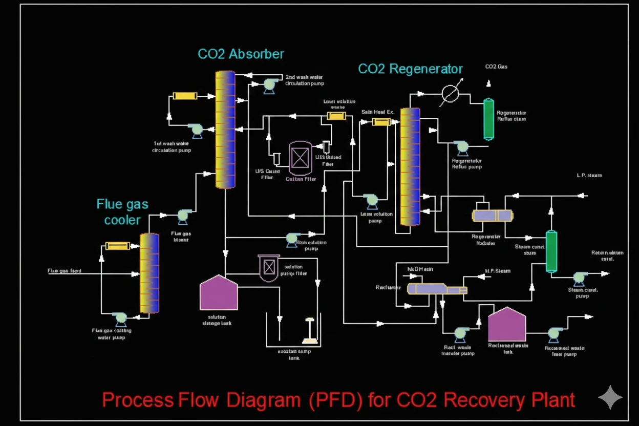
Process Flow Diagrams (PFD) – CAD Drafting Services
As part of our CAD drafting services, we create detailed Process Flow Diagrams (PFDs) that serve as the foundation for designing efficient piping systems. A PFD is an unscaled schematic that illustrates the flow of fluids through the piping, specifying the type of fluid, flow rates, major equipment, basic operating conditions such as pressure and temperature, equipment capacities, and all critical valves including control valves. PFDs clearly show the relationships between major equipment and the connectivity of the piping system, providing a clear overview of process flow and operational logic. While pipe sizes, classes, instrument tags, and detailed components are not included at this stage, the PFD provides the essential data that is later transferred to detailed Piping & Instrumentation Diagrams (P&IDs) or Piping Engineering Fabrication Sheets (PEFS), ensuring accurate, efficient, and coordinated design and construction.